Transformers with low no-load losses
Share

Introduction: Why losses in transformers are so important
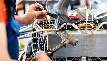
Transformers are inconspicuous but indispensable components of our energy system. Without them, it would not be possible to transmit electrical energy over long distances. By transforming the voltage to a higher level, smaller currents flow, which reduces the voltage drop across the transmission line. Without voltage transformation, the consumer may no longer see any voltage because almost all of the voltage drops across the line. In addition, a transformer can be used to adjust any AC voltage to the desired voltage of the load. They therefore ensure that electrical energy can be transported over long distances and converted into usable voltages – from large power plants to domestic power outlets.
But as powerful as transformers are, they do not operate without losses. During operation, losses occur in the form of heat. The energy is literally burned up. These losses have not only technical but also economic and ecological consequences. This is because every energy loss means more electricity production – and thus often higher CO₂ emissions.
Of particular importance here are so-called no-load losses, i.e., losses that occur even when the transformer is not supplying any load. In this article, we explain how these losses arise, what role the materials used and the design play, and why efficient transformers are a key component of energy efficiency and sustainability.
What losses occur in a transformer?
A transformer essentially has two dominant types of loss:
- Winding losses (short-circuit losses)
Core losses (no-load losses)
Winding losses
Electricity flows through the copper or aluminum windings of a transformer. This electricity causes ohmic losses as well as skin and proximity losses. The following applies: the greater the current, the greater the losses. The easiest way to determine the approximate winding losses is to short-circuit the output side of the transformer and increase the input voltage until the rated current is reached in the short-circuited output side. This is why winding losses are also referred to as short-circuit losses.
Core losses
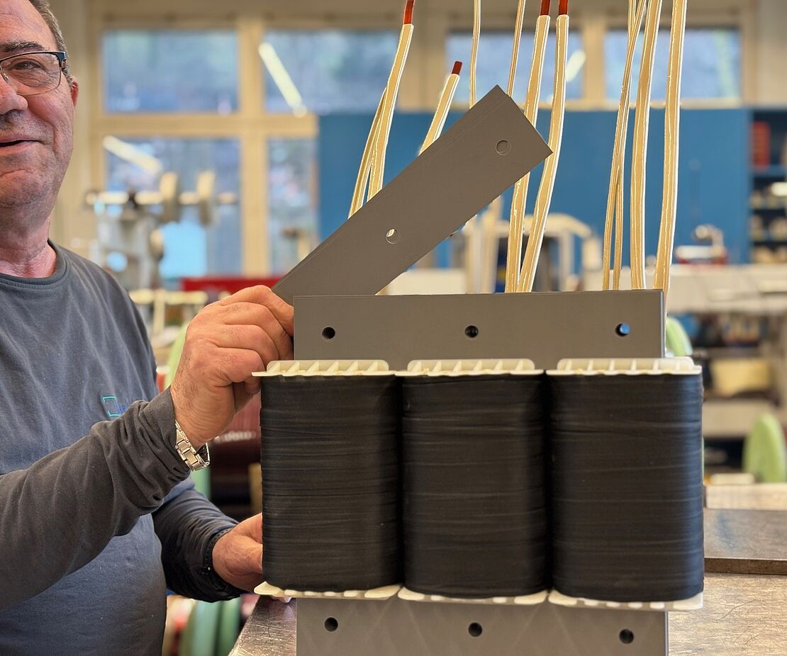
Even more interesting are the core losses that occur in the magnetic core of a transformer. Almost all transformers have a magnetizable core, which can be made of iron sheets, ferrites, or modern nanocrystalline materials. The losses in the core are caused by the magnetic realignment in the core over a network period. They are linked to the input voltage and the core volume and are therefore independent of the load. They occur even when the transformer is operating in idle mode, i.e., when no consumers are connected. This is why they are also referred to as no-load losses.
Precisely because transformers are permanently connected to the grid, these losses are the focus of attention when it comes to energy efficiency
How do idle losses occur?
No-load losses consist of two main components: hysteresis losses and eddy current losses in the magnetic core.
1. Hysteresis losses – the “magnetic memory”
Every conductor through which current flows generates a magnetic field. This magnetic field is used in the transformer to transfer energy from the primary winding to the secondary winding.
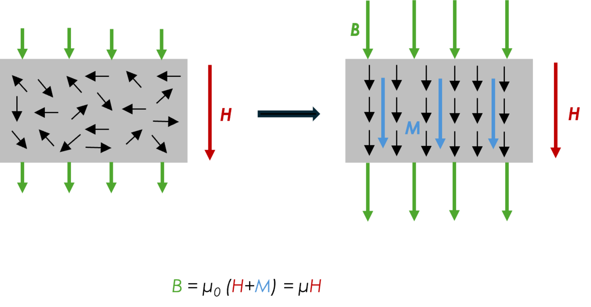
The magnetic field, also known as the H-field, causes the elementary magnets in the core to align themselves. The more elementary magnets in the core point in the same direction, the greater the magnetic flux in the core. In other words, the magnetic conductivity increases. This is why the H-field concentrates on the core, while the magnetic field in the air is often considered negligible.
To illustrate how the elementary magnets align themselves in the core, imagine two permanent magnets lying on a table in random positions. As soon as the first permanent magnet (with the corresponding H field) approaches the second (in our example, the elementary magnet), the second aligns itself as if by magic.
The additional magnetic field resulting from the alignment of the elementary magnets in the core is called magnetization or M field. Expressed in formulas, the following applies:
B = μ0 (H+M) =μH
Here, B is the magnetic flux density, μ0 is the permeability in a vacuum, and μ is the permeability in matter. Permeability can also be interpreted as magnetic conductivity.
Once all magnetic dipoles in the core are aligned, magnetization no longer increases. If the magnetic field strength H is then increased further, the core behaves like a vacuum (B = μ0H). In this case, we refer to magnetic saturation.
If the magnetic field strength in our consideration is reduced again, one might assume that the magnetization also decreases. However, the core is magnetically inert, which means that the alignment of the magnetic dipoles in the magnetic core remains unchanged. This means that a magnetic flux and thus also a remanence flux density Br remain. In order to destroy the residual magnetization, a negative magnetic field must now be applied. This corresponds to the so-called coercivity field strength Hc. Once a material has been magnetized, a field always remains.
Consequently, the field-free state only exists at the very beginning. In our analysis, we first apply the full negative magnetic field strength, then reduce it to zero, and finally increase it to the full positive magnetic field strength. This gives us the complete hysteresis curve, which is shown in the following graph.
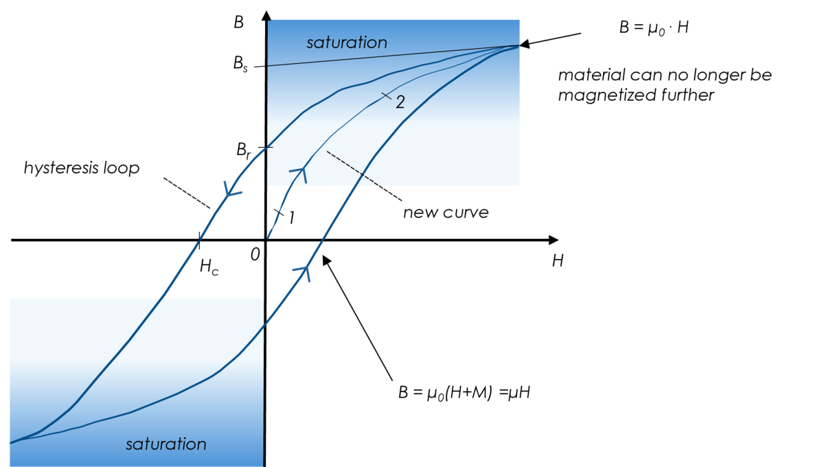
Steps 1 and 2 (light blue path) are called the new curve and are only valid at the very beginning. After that, the dark blue path is valid for the B-H relationship (hysteresis loop). Hc is the coercive field strength and refers to the negative field strength required to reduce the magnetic flux to zero, i.e., B = 0.
However, remagnetization is associated with losses. The larger the enclosed area, the greater the losses. How these can be reduced will be described later. Next, we will look at the second dominant type of core loss—eddy current losses.
2. Eddy current losses – electrical circuits in the core
The second major loss phenomenon is eddy current losses. Just as the time-varying magnetic field induces a voltage in the secondary winding, voltages also occur in the core. Since iron is a conductive material, so-called eddy currents flow in the core. The ohmic losses of these currents are referred to as eddy current losses. In a solid iron block, the eddy currents become so large that the core begins to “boil” at a load of only about 0.5% B. This can be remedied by using thin, insulated sheets that limit the eddy currents. The thinner these sheets are, the lower the eddy current losses.
Technologies for reducing no-load losses
In the development of modern 50 Hz transformers, there is a strong focus on minimizing these losses. Two key approaches are:
Grain-oriented sheets
Special manufacturing processes are used to imprint “grain-oriented” structures into the sheet metal. This causes the magnetic field to be guided preferentially in a certain direction. This means that less energy is required to align the magnetic dipoles, resulting in a significant reduction in hysteresis losses.
Thinner sheet metal packages
The thinner the individual sheets of the core package are, the more eddy currents are limited. However, there is an economic trade-off here:
Thinner sheets are more complex to manufacture.
Thinner sheets increase the number of sheets per core, which increases the manufacturing effort required for nesting.
Practical example: Increased efficiency through low-loss transformers
A simple calculation example based on a three-phase 40 kVA transformer illustrates the scale involved:
The difference in no-load losses between a standard transformer and a low-loss transformer of the same size is more than 210 watts (i.e., over half a percent of the rated power).
If this transformer runs in the grid all year round, the losses add up to over 1800 kilowatt hours – enough to cover the annual electricity consumption of a refrigerator.
Fazit – Kleine Verluste mit großer Wirkung
At first glance, transformers may seem unremarkable, but their efficiency has an impact on the entire energy system. One key factor is no-load losses, which can be significantly reduced through the use of modern materials and technologies.
- For engineers, the following applies:
The oversizing of a transformer must be carefully considered. This is because as the core volume increases, so do the no-load losses, which add up over the entire operating time. In return, it can be clarified how long the transformer can be operated under overload. A short-term peak load can be accepted without any problems under certain circumstances, as a transformer has a large mass and therefore overheats very slowly.
- For buyers, the following applies:
Quality pays off. A transformer with low no-load losses and high efficiency is cheaper than a cheaper model over its service life of more than 30 years. The energy costs saved far exceed the higher investment costs. Use our sustainability calculator to find out more.

Would you like to learn more about modern transformer technologies or do you need advice on energy-efficient solutions? Then get in touch with us! Together, we can shape a sustainable future.